Quantcast
Channel: Making Electronics
Viewing all 42 articles
Browse latest View live

DIY Car Bluetooth A2DP

$
0
0
Does not have bluetooth in your car? No problem, let's do it yourself.
I had a spare iPod / iPhone dock Bluetooth A2DP receiver, never used. So I decided to open it up and fit into car 12v plug with aux out.
Here what it looks like when new:

When opened there is one pcb with OVC3860 Bluetooth chip. Actually it sounds better than ISIS chips. That why I decided to use it.
I desoldered 30 pin ipod connector with heat soldering gun.
Backside has some testpoins, maybe useful to easy solder wires for aux and power.
I traced 30 pin connector pads to testpoints and found out that this thing needs 5v power and has left, right, audio ground and 5v in and power ground on testpoints.
I've opened 12 car plug, removed guts and tried to fit this pcb in, no fit =( But with desoldered 30 pin connector there is much unused space on pcb, so I cut it to fir nicely.
Soldered 5v linear regulator and put heatshrink over it later.
Wired power and AUX out to 3.5mm female socket with screw mount and it is done.
Forget to take picture of it when closed, but there is nothing special, just plug hole visible. Sounds nice, but becomes hot almost instantly. This thing eats 100mA when receiving sound and 60mA when idle. So linear regulator works on the edge, it is rated for 100mA. But chip itself gets hot too, not sure why. Anyway I connect car AUX to this plug and have Bluetooth now.

OBD II Bluetooth PowerUp

$
0
0
Just upgraded my Bluetooth OBD II adapter with class 1 power module. Now I can diagnose a car sitting at home.
You can get bluetooth OBD2 adapters from Amazon but neither of them has class 1 power bluetooth module with ceramic antenna! =)

Game Boy Color Loud Sound Mod

$
0
0
Update: published schematics and pcb design files for Eagle and Gimp. Make your own pcb and respect the license =) Take a look: http://code.avrnoob.com/gameboy-color-quality-amplifier/

Recently I've got used Game Boy Color and noticed lack of sound volume, it is barely audible. So I tear it down and pulled speaker out, it was all rusty.


 I had a speaker for Motorola L7/L6/L2/L71/K1-GSM/V8 on hands and soldered it in. So this is fixed sound. But it is still not loud at all, so low volume, I had to use my headphones instead. Oh and there is loud hiss noise, guess it's coming from power supply. I had to do something with it =)
I looked in my parts bin and spotted TPA2000D1 - a class-D mono amplifier from TI. It is 2W power rated with programmable gain and class-d is pretty efficiency means low power consumption.
After some time pcb was made.

I used schematics from datasheet but in the final version I changed 1uF bypass cap and other 1uF caps to 10uF and added 0.1uF. Also I had to change 120k resistor in oscillator circuit to 180k to keep frequency below 300 kHz, it was 330 kHz with 120k resistor.

Powered up ok first time wires connected and sound now is much louder even with gain of 6 dB but then I set it to 12 dB by moving one resistor to outrun any ambient noise. This is max before clipping I guess. Unfortunately noise hiss did not gone away and become even louder on high volume, so this is power supply. Game Boy Color is powered with two AA batteries. But it has switching step up power supply with 15V and 5V output, this makes noise because amp is powered from 5V. I had to add additional 470uF cap to 5V power rail to make noise go almost away, now it's barely audible on max volume.

Amplifier pcb moved over speaker and case closes nicely.

Amp barely visible inside. This Game Boy Color now definitely has Hi Fi sound =)

PIR Motion sensor relay fast repair

$
0
0
Recently my motion sensor lights switch went bad. I opened it up and found that main ic is dead, but relay and relay transistor is ok. So I ordered really small PIR Sensor Module to fit it in place of dead ic. That ic was LP8072C which is a pir controller and it support light intensity sensor which is just a Photoresistor. So my motion sensor does not switch relay in daylight, designed for lights switching.
Pir sensor module I've got does not support photoresistor, so I had to design it in myself. What I've done is connected photoresistor to the base of relay switch transistor and second lead to the ground. With a base resistor which was on pcb already it makes a strong pulldown to transistor base. So when it's a daylight, photoresistor changes it's resistance to about 220 Ohm which prevent transistor to switch relay. I had to remove some parts from original pcb which interfere with photoresistor. An I removed LP8072C too.
Then I removed actual pir sensor can from module pcb and removed connectors too. Wired pcb pads to old pir sensor can on original pcb and to power and wired output to the output pad of LP8072C ic.


Then I glued sensor module pcb in place. Works ok except this new sensor has short keep relay on timeout, but whatever. This can be adjusted I guess, ic on sensor module pcb is unknown, no markings, it looks like sanded.
As you spotted there is no power supply as we used to see. It's just Live wire through 0.47 uF 250v cap in series with resistor to diode bridge. Then to 25v filter cap then to regular diode to drop voltage a bit then to zenner diode to get 5v with filter cap. It's a low power supply. Sometimes it's used inside cheap led light bulbs with many leds. This red 0.47 uf cap is half dead already because it's rated to 250v and as you know 220v mains has 315v sine peaks. It's capacity is 0.2 uf and it still works.

Chinese electronics recycle fun or what's inside gsm to landline phone terminal

$
0
0
Here we go. I have a simple gsm terminal for landline phones, so I can call from regular analog phones through gsm network. I'm using it in low signal area with external antenna.
So one day I decided to look what's inside of it. I was thinking there would be some kind of gsm modem inside and analog support electronics etc. But found some interesting stuff.
Here how this thing looks, nothing important just grey box with gold antenna output sma socket.

Now let's take a look inside:

Yes, it is a gsm cell phone pcb inside! With phone battery for backup power. This thing is powered by nuvoTon W78E052DDG mcu. Which has 80C51(52) core. Never heared of them yet, but they make Cortex-M0 mcu and other ARMs too. I guess it is connected to the phones serial port.


Wires soldered directly to pcb connector.


Looks like Nokia or SE connector to me.


Wires soldered directly to phone external connector.
Phone pcb screwed to terminal housing posts, so this housing is made for this particular phone pcb on purporse. It means some kind of cellphones recycling =) Chips on phone pcb has date codes leading to 1999.


Wires soldered to the phones sim socket leads to a new sim socket on bottom side of terminal main pcb.


Some unknown chip under pcb.


Here must be some know-how, otherwise I don't know why they sand those chips markings.


LCD board glued in place =) This LCD board is connected through serial data line, may easily be reused. There is a black blob lcd controller on pcb.


LCD itself actually has a good contrast.

I had used a cell phone as wireless terminal to send sms alerts. But I never though this would be used in actual manufacturing =)

Update: as requested I pictured main pcb bottom side:


Gameboy Color Quality Sound Mod update

$
0
0


Here we go again about sound in the Gameboy Color handheld.

I've made new pcb with new smaller amp ic. So this is a new leaf style cut pcb and it will fit just over speaker in the speaker cutout. Virtually takes no space.
I've already tested it, sounds great. Set to 12db gain.


Here how it looks when wired up. Needs only 3 wires to install (+2 for speaker).

I can make it into a kit now.

TI LaunchPad RDA5807P (TEA5767) FM Radio inside a pc speaker

$
0
0

This is about my old project when I firstly received TI LaunchPad kits.

An encoder used for tuning to frequency. I'm using an encoder with push button which used as search function to auto tune in fm station. Couple of caps used for debounce..

I used old pc speakers, which already has amplifier inside and a transformet to power this fm radio. Just added 3.3v linear regulator in dead bug style.


I had RDA5807P fm radio module from china. RDA5807P is a clone of TEA5767 including i2c commands and functions etc. Read the datasheets for rda5807p and tea5767. Any similiar module will do.


I then wrote a driver for rda5807p and application code to control frequency with encoder etc. As for PLL tunning I had to precalculate a table for fm radio spectrum because my msp430 chips only had 2kb of flash.
Cram it all inside the speaker housing.

And the whole look.
Antenna wire goes out from speaker's "phase inverter" hole.

RDA5807P driver and application is open source and available at: TI LaunchPad FM Radio repository.

Let's make a Wireless Speaker

$
0
0
Found some unused parts laying in the box, let's make something.
How about battery powered wireless speaker, portable speaker for your phone or player. What wireless technology I going to use? Bluetooth ofcourse.

Let's take cheap speakers like this for example Pyle PLMR24. I bought these to use outside, but...
look inside:

"Completely Water Proof" with a big hole in the front. I thought it should be sealed. Do you see advertised "Capacitor Crossover Network"? I don't. Just wires. Those "1.75" Wide Dispersion Cone Midrange" and "1" Super Dome Tweeter" made of 2 identical piezoelectric transducers, have a spare.
I'm going to listen mostly talk podcasts on this wireless speaker, so, doesn't matter much.

As a bluetooth A2DP receiver I'm going to use KRC 86A/B V3.2 but any other A2DP bluetooth modue will do. KRC has CSR BlueCore5 bluetooth chip and making a bit of hiss noise when connecting.

Next I need a sound amplifier. I took TPA2005D1 ic known from my GBAmp project. It's only 1.4W power but for my purporse it is enough. And it is class-d very efficient amplifier, good for batteries. I'm going to use 18650 li-on single cell battery.

I measured width of the bluetooth module pcb and designed amplifier pcb to be glued on top of module pcb. Then I made a couple of amplifier pcbs at home with most working method, one for backup.
There are many capacitors with small capacity, I have not any bigger capacity caps in stock.

Then glue it with double sticky tape on top of bluetooth module. And connect wires.
As you can see the final amplifier version configured to 18dB gain.

Add a battery holder, tape and glue it all to the speaker back.
You can see blue led glowing, means it is conneceted. I'm thining to put it all insude and add charger pcb and a swith, that will look much better. But for now, it works s is. Battery will last for several days I guess. I already used it for 10 or so hours.

New Enhanced Gameboy Color Loud Sound mod

$
0
0
New enhanced version of Gameboy Color quality loud sound mod is ready. It's called GBAmp2s. It's ready to order at tindie.com

Difference with the previous version is that it is using different amplifier ic with more gain. Also it uses stereo audio signal from Gameboy. And you do not need to install additional capacitor to remove loud hiss/hum from the speaker. A bunch of quality capacitors already installed on the GBAmp2s mod pcb.


Bare and assempled pcbs:
Back:
And here how it looks installed in the Gameboy Color:

Yes there are couple more wires to get stereo audio to pcb. This new pcb design has all connections marked on silkscreen, so it's easier to install.

New pcbs are made by hqew.net which service I will review later.

Gameboy Loud Sound mod for DMG-001

$
0
0
People are asking if this GBAmp2s mod pcb will work for original DMG-001 Gameboy.
Yes it will, take a look:
Mod pcb has to be installed in different place otherwise case would not close. Also longer wires. Works great. GBAmp2s at tindie.com.

Game Boy Micro battery upgrade

$
0
0
Can you play your Game Boy Micro for several hours? I can't till now.
This blog is all about diy, so let's make a new battery for it.
In my region original battery cost a lot and I searched for similiar size lithium battery.
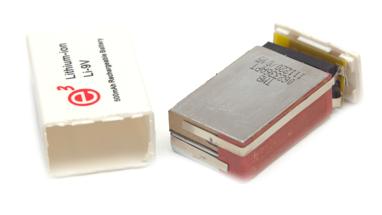
 And found this 9v rechargable lithium battery.

I thought there are 2 3.7v lithium cells in series inside and I was right. You can actually build two batteries for the price.
Protection circuit inside which prevent deep discharge and overcharge.
I cut out protection pcb and split battery cells.
Then I unwrap original battery to compare old and new cell sizes.


Checking how it fits inside Game Boy Micro.

New cell is half mm thicker, but it's a no problem.
Then I soldered wires from original battery and tested charging and playing.

I also added a sticker from original battery, so it looks almost original =)
New cell has a bit more juice too. Works and chrages great, as expected. Battery cover sits ok.


UNI-T UT61E RS232 serial interface cable to USB diy mod

$
0
0
I'm using my UT61E a lot. One great feature it has is that it can send data to pc for data logging. And it has interface cable included in the box with no additional cost. But the cable is RS232C compatible using DE-9 connector and +/-12V logic levels.
Do you have DE-9 connector on your laptop? I don't :) You obviously can use that RS232 to USD Adapter cables, but DIY guy can make his own cable, right? Add bluetooth too perhaps?
Let's take a closer look at the supplied RS232C cable:

From the first look it has only one working "eye". Which means there is no connection from PC to the meter, easier to hack then.

What's inside:

Definitely only one RX IR sensor diode used, TX circuitry is not populated.
Here is a schematics I reversed from the pcb:


This thing pulls up RX line when IR diode senses light from the meter. UT61E sends inverted serial signal to its IR led.
There is a bit of space inside this sensor box. And I need to fit a circuit inside, which senses IR light and pulls down RX line from 3.3V to Ground. This is classic UART serial interface.
Unsolder everything from the pcb except IR sensor diode.
This is new schematics using 2 n-channel mosfets, any general purporse mosfets will do. I used 2N7000.


R1 needs to be set lower than original because we are using 3.3V now and there is not enough juice to turn Q1 on fast enough with 4.7k.
OK, then I made this piece of art:
This fits perfectly inside original enclosure. New cable needs only 3 wires: +3.3V, GND and RX, I cut the rest. You may be wondering why I call it RX, well this is how DE-9 was wired. RX means PC side RX pin.

At this stage you already can connect UT61E to the microcontroller or Arduino or anything else which understands 3.3V UART. But I started it as USB mod, so we continue.
I have some CP2102 Serial UART TTL USB converters laying around and this is enough for this mod. Just connect that 3 wires and there we go.
Female header used so I can disconnect CP2102 converter and use it anywhere else.

Raw output from the meter:


Correct serial port settings for this meter are: speed 19200, bits 7, stop 1, parity odd.

That's it.
But, there is more! You can even add a Bluetooth feature to this UT61E multimeter. It's easy as soldering 6 wires to some serial bluetooth module with this mod.
UT61E with Bluetooth, sounds great! Interested?

Let's quickly repair Nintendo 3DS shuts off with popping sound when fully opened

$
0
0
Ok, so I recently got this heavily used Nintendo 3DS which was not turning on fully. Blue light comes on then it makes popping sound with a little backlight flash and shuts off.
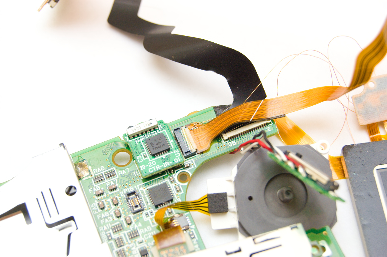
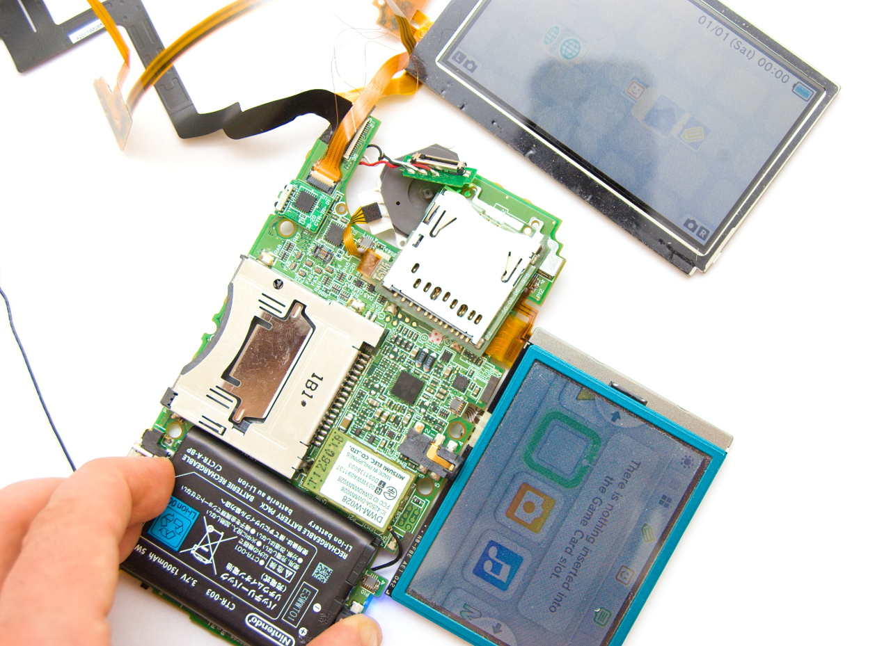
I tore down it into pieces while searching for faults. Found broken touch screen flat flex cable.
Also I found flat flex (ribbon) cable with some traces been broken in the top half of the 3DS and that was the culprit of popping sound and shut off.

This flat flex (ribbon) is connecting top screen backlight, 3D control ? and speakers. Any fail in the backlight circuits of top or bottom screen and 3DS will shut off with popping sound.
So it's easy to fix, just order a replacement cable. No way :)
Checked with multimeter and found there are only 2 traces broken.
I took some hair thin enameled wires. I then scraped off flat flex (ribbon) traces to copper at the connector side and soldered wires there.

Also soldered these wires to connector on lcd side.

And it works :)

I then glued wires to the flat flex cable with tape.
Putting all that flat flex (ribbon) cables back through the hinge was huge pain though. 

GBAmp2 wiring guide for DMG-001 console

$
0
0
GBAmp2s wiring guide for DMG-001 classic Nintendo console is ready and available on GBAmp website.
Basicly it's this picture only :)

Handheld Famicom / NES Clone Teardown

$
0
0
So there are numerous Famicom / NES clones, some of them are portable handheld versions.
Let's see what's inside one of them. This one has a cartridge slot along with "many" built-in games.

It has li-ion battery, usb charge cable and tv out cable included, so you can actually play it on tv. But it lacks of second controller and does not have a select button. In some games you can not select "continue" because you do not have select button :)

Single pcb design. LCD is not 4:3 but image does not look stretched.


This black blob is the main CPU+PPU chip, unknown.


Edge connector for cartridge on the back. USB battery charging circuit. Main crystal. And there is 16Mbit CMOS flash where built-in roms are stored. This pcb can accept flash in different packages. 3 color wires are soldered by me, it's for speaker and battery connector, old wires were rusty with failed soldering job.


This is to compare cartridge size with GameBoy cartridge, very small.

Inside there is the same 16Mbit CMOS flash chip without any fancy mapper chips. It just replaces a built-in flash when inserted.

GBAmp2s at kitsch-bent.com

$
0
0
Great news for US GameBoy (Color) loud sound fans :)
GBAmp2s will be available at kitsch-bent.com soon. Faster shipping for you.

Let's make Wireless Gamepad / Controller for Famicom / NES Part 1

$
0
0
I'm slowly restoring good old Famicom console.
It was in partly working condition. Some games was able to show title screen but not start, or not start at all with grey screen. This was hard to find fault. But I managed to fix it, it was one of the address lines trace broken in the inner pcb layer. Added one wire and got it working.

Now to the topic.
Who need wires this days right? Less wires is better always. So I decided to design and make a mod for stock Famicom controllers to make them wireless.
Famicom has official wireless controllers but they were using crappy IR and you need to point it to console every time. I want to make RF wireless controllers using that fancy 2.4GHz ISM band.

I'll make a prototype for a newage Famiclone console to test things out (chinese D99 model, single chip clone).
This projects has two sub-projects. First one is for transmitter which will be inside Famicom controller with battery and USB charger. Second one is for receiver, prototype will use Famiclone controller port (Famiclone has removable controllers), you just plug in receiver or plug in wired controller.

Famicom controller has pretty simple schematics. It's a single shift-register parallel input, serial output and 8 pull-up resisters. It can use HEF4021B ic or similar. Famiclone controller uses black blob ic, which is unknown, it's the same shift register but with built-in pull-up resistors.
Stock controller schematics should look like this:

To make a transmitter I need to "read buttons" like a console, pack it into a packet and send it to receiver. To make receiver "plug and play" it should emulate controller. When packed received and when console read buttons it will respond as controller.

In the next part I will select hardware for transmitter and receiver.

Let's make Wireless Gamepad / Controller for Famicom / NES Part 2: Hardware

$
0
0
What hardware do I need to get this project done faster? I need 2.4Ghz transceiver module which I can connect microcontroller to. The same module for a gamepad and receiver. I need very small and thin module to fit inside a gamepad case.
I thought to use ever popular module with NRF24L01 transceiver ic. But I don't have small one, one with 8 2.54mm pin connector is huge and will never fit inside a gamepad.

But I do have really small module with NRF24L01 clone ic called BK2421 (made by BEKEN). Module called RF-2400-NANO made by INHAOS Technology Co. This will fit nicely. It has the same configuration registers, but has 2 register banks. Second bank is only to configure BK2421 ic.


OK. Now I need a microcontroller to make it all work. I have 2 spare MSP430G2452 in VQFN package. This is enough to make proof of concept.

Also I need a battery for gamepad, lithium rechargeable battery. I will use MCP73831/2 charging ic from Microchip to charge this battery from USB.

In the next part I'll make schematics for transmitter and receiver modules.

Let's make Wireless Gamepad / Controller for Famicom / NES Part 3: Schematics and PCB design

$
0
0
Here goes schematics and pcb for transmitter which will be is installed inside a controller shell.
Battery charging current set to ~200mA. There are 3 leds. Red(Orange) is for charging indication. One green for charging end indication and second green is for debug indications. There are 4 smd connections. +5v input for charging. Battery connection. SBW for programming. And controller pcb wires connections.
PCB is doublesided with 22x27mm size. PCB and parts footprints are designed to be hand soldered.


And schematics and pcb for receiver module which will be installed inside NES / Famicom or soldered to the original 7-pin or Famiclone 9-pin (or 14-pin) controller plug for plug-and-play. As I said this receiver will emulate original controller interface, so it's just ready to go. PCB also has the same smd connections for power in, SBW and controller interface. And green led for debug indications. Also to note, NES / Famicom has 5v controller interface signals but used MCU can handle 3.3v only so I used voltage dividers to limit maximum signal voltage and current.
Receiver has slightly bigger PCB with 22.6x27mm size.


For the next part I will manufacture transmitter and receiver pcbs at home and solder parts on. Also will try to fit it inside a controller shell with battery. And will use receiver pcb with Famiclone console for POC.

Oaxis InkCase for iPhone and Note II Teardown

$
0
0

Today I'm going to teardown a pair of Oaxis InkCase thingies. It is a protective case for your phone which has a second screen and the screen is eInk type screen, black and white. This type of screens used for eBook readers like Amazon Kindle. So in theory this "case" should work much longer than your phone on it's battery. A case connects to your phone through Bluetooth 2.0 for N2 and through Bluetooth BLE for i5.
I received these units for beta test in Jan 2014 and found them unusable at that time. Especially N2 case which was chewing batteries like crazy, it would not hold a day without recharging. Also often loosing connection without being able to reconnect without disabling and re-enabling bluetooth first. So I wrote it all to the guys at Oaxis and put units away.
A little tip on how it works. It's very simple. Phone just sends a single image to the case through bluetooth, that's all. All the image compositing done in the phone's app.
Now I see they are released new InkCase Plus model which is designed to fit to almost any android phone.
Enough waffle, let's tear it down starting with N2 model.
 So basically it is just a refitted eBook reader. It has 4 buttons, left, right, select and hidden reset. You can switch to previous images that phone sent. Images in this case is screen updates, like weather, pictures and so on. There is no processing on this device except showing images.
Back side made of smooth plastic with will not scratch your phone.
As you can see, inside it has a generic eBook SoC Allwinner F1 E200 and supporting circuitry. Also they added bluetooth in the corner. 820mAh battery. So this is it for N2. Nothing exiting, right?

Next i5 model.
Again, back is made of very smooth plastic. Take a peek inside.
Battery is half capacity of N2 model 460mAh. But this case is using BLE which is much lower power than Bluetooth 2.0.

Ok, the circuit is completely different to N2. This one has a Rockchip RK2818 SoC which used in low-end android phones. Also to note, i5 model has only one single button.
While I was playing with i5 disassembling it and reassembling, trying to charge a battery etc. I somehow entered into a recovery mode. And what do you know, this thing has an actual Android OS inside. So iPhone has a protective case which has Android in it :)

Viewing all 42 articles
Browse latest View live